")
")


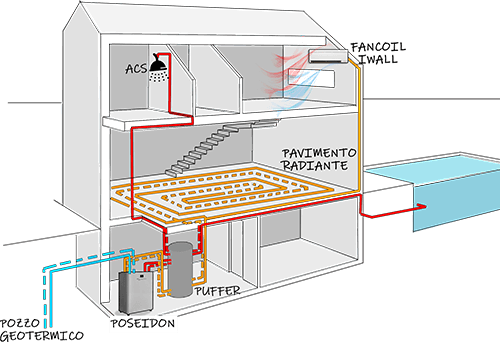
The POSEIDON water-water heat pump units are designed for applications using radiant panel heating systems or low temperature applications such as suitably dimensioned fan-coil, thermal ventilation and AHUs for delivery temperatures of 50°C.
The units can be installed for applications using borehole water or groundwater and also for applications using a geothermal probe. All versions are fitted with high quality modulating circulators and Twin Rotary inverter compressors that allow the system to operate according to the energy required by the system.
The compressor and circulators are continuously regulated by a programmed control unit with an internally developed control logic.
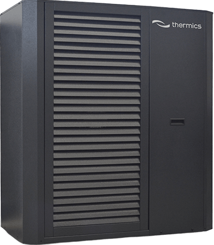
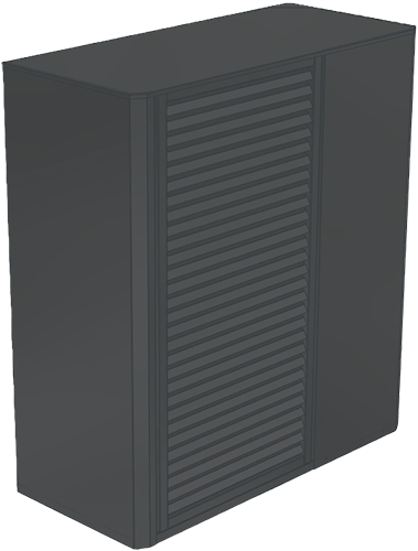
The POSEIDON units have a vertical powder coated galvanised steel structure. They are characterised by high efficiency with integrated management of the circulator, which allows high temperature hot water production with a three-way diverter valve on the boiler and has the option of using a backup electric heating resistance, or alternatively, the integrated management of a circulator and heat exchanger dedicated to DHW production.
Geothermal homes
- Geothermal energy is a stable and lasting source. It is essential to use this energy correctly in order to achieve the best heating comfort at the lowest cost.
- The inverter technology combined with the "plug & play" concept make the geothermal plant slim, dynamic and completely flexible!
Technical specifications
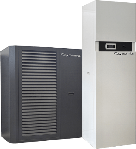
Compact water-water heat pump with electronic circulator on both the source and system sides and Twin Rotary Inverter compressors, with a cutting-edge design and high COP. The heat source is water whether it is from a borehole or groundwater, also using a geothermal probe. Low noise is guaranteed by an intelligent control system that regulates the speed of the compressor and fan according to actual requirements. In addition, the use of anti-vibration mountings for the compressor and multi-layer noise insulation on the casing mean that noise is reduced to a minimum. The units are equipped with a buffer tank that makes them particularly versatile and can be connected to existing systems that are connected to a hydraulic separator.
Controller
The control unit consists of an Evco unit and can be combined with a highly intuitive touch-screen controller with which all the operating parameters, set points and usage settings can be controlled. The storage tank is charged at a set point for DHW and with a heating or cooling curve for the heating / cooling side. Other possible auxiliary controls:
- Auxiliary electric heating elements in the circuit or the storage tank
- Auxiliary external sources (existing gas, electric and other boilers)
- Input for activating a second set point if low-cost energy is available (e.g. from photovoltaic inverters)
- Option of controlling a 3-way valve, recirculation pump or transfer pump
The units can have either 4 or 6 pipes (2 of which are on the source side), the latter can control a high and low temperature circuit simultaneously. The high temperature circuit has its own circulator, the flow rate of which is regulated by the controller. In summer, the high temperature heat exchanger will operate as a desuperheater, improving overall performance and producing hot water by recovering energy that would otherwise not be utilised. The speed of the compressor, fan and circulators is continuously regulated by the control unit.
Structure
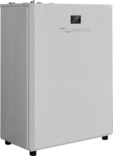
The units are made of powder coated hot-dip galvanised sheet metal, the structure is self-supporting with removable panels to make inspection and maintenance easer.
Cooling circuit
The refrigerant gas used is R410A (R134A on request). The unit is fitted with inspection ports to enable technicians to check that the cooling circuit is operating correctly.
Heat exchangers
Both the source-side and system side exchangers (also for a desuperheater, if present) are made of braze-welded stainless steel plate that allows the amount of refrigerant gas to be reduced to the minimum, maximising efficiency through the large heat exchange surface.
Circulators
The electronically controlled circulators modulate the flow. The speed of rotation is continuously regulated by the control unit.
Control and protection
The unit is equipped with a series of alarms designed to protect it from faults. These are managed entirely by the control unit that makes them available and accessible. It is also possible to access the controller via the control unit if you need to make any adjustments.
Testing
All units are fully assembled and wired. They are inspected to high standards, undergo leak and vacuum cycle tests, and are filled with an eco-friendly refrigerant. They undergo a complete functional test before being delivered. All units comply with European Directives and have a CE marking and relative certificate of conformity.
Technical specifications
Technical Documentation